How to build a needlessly complicated weather clock for under 10 euros
by Andrew
2014-02-18 05:29:54
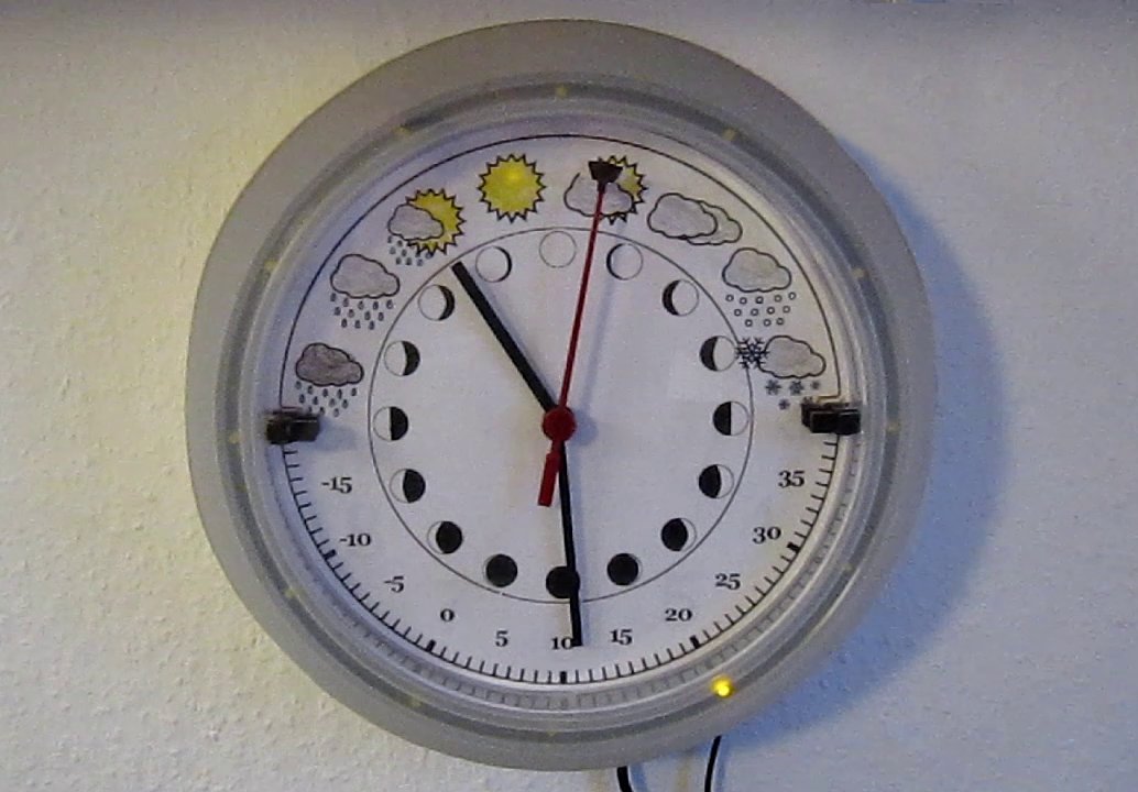
So what the hell is a weather clock? It's something that looks like a clock, but shows the current temperature and weather (and in my case also the phase of the moon). There are different ways of doing this. In my case it gets the information online and the display is actually built out of a clock.
From the beginning, this was a solution in need of a problem. I got the idea a while ago that a usb keyboard could be used as a cheap computer interface. Then arduinos got cheap and mooted the whole idea. But I was never one to let go of a stupid idea easily. To cut a long story shortish, I was looking for a project and decided to build a weather clock with a budget of 5 Euros. For that much money I couldn't buy anything big, so I'd have to make do with what I had lying around. The brains are an OLPC, the interface is a controller from a broken keyboard, and the display was going to be a clock I happened to have, but I ended up buying a slightly bigger one for 2 Euros from ikea.
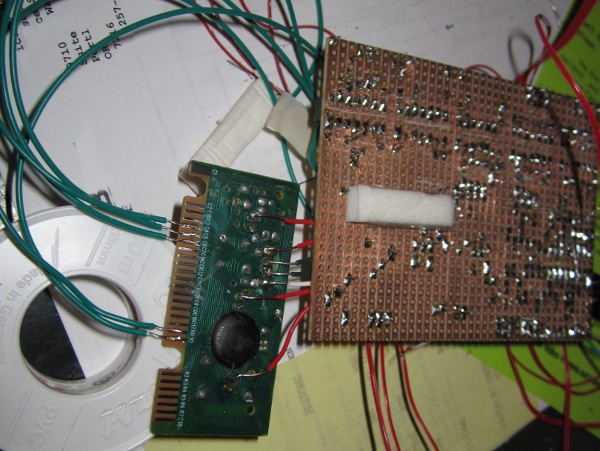
The keyboard controller
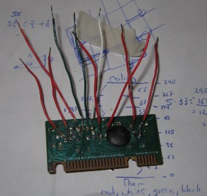
It's easy to put information into a keyboard, but how do you get it out? Keyboards have three leds which can be toggled on and off by software: caps lock, number lock and scroll lock. I figured I could tap into them and use one as clock, one as data and one as latch to push data to shift registers. It didn't quite work out that way.
First thing I had to do was figure out how to toggle the LEDs in software. Since I was using the OLPC, I wanted to program in Python. There is a library for Python called python-keyboardleds, but I could never get it to run, so I wrote my own.
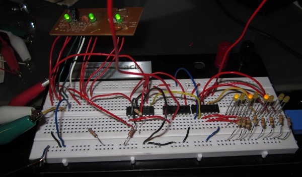
Now that I could toggle the LEDs at will, I needed a usable signal from them. After measuring with my multimeter, I found that one LED line stays at 5 volts and the other toggles between 5v and about 3.8v. That's no good by itself, but using an op amp I had lying around as a comparator gave me logic levels. So far so good. I bought four 8 bit shift registers (total cost 96 cents) to theoretically give myself 32 bits of output data. I wired up one LED output as clock and one as data and … I got garbage out. Each toggle of the clock led registered 2-5 clock cycles. It turns out the LEDs have a lot of bounce when they're turned off or on. I tried adding a Schmitt trigger, RC filtering, blah blah blah. Finally I solved the bounce by using one shift register as a signal buffer and the output of that as the clock to the remaining shift registers. This tied up another LED and halved my data rate, but it works, at a blazingly fast 40bps (that's bits per second). Since I had lost my latch line, I solved this by feeding the last bit through an inverter to the clear line of the shift registers and using the second to last bit as an enable. In this way, nothing happens to the motor until the enable is high (i.e. all the data has been received). Then, as soon as the clock changes, the high enable bit moves to the last bit, which becomes low on inversion and clears all the shift registers. More complicated, but it works. Moving on.
The Clock
I bought a RUSCH Wall clock from ikea (cost: EUR 1.99), which exactly fulfilled my criteria of being:
A. Cheap
B. Easy to take apart
C. Cheap
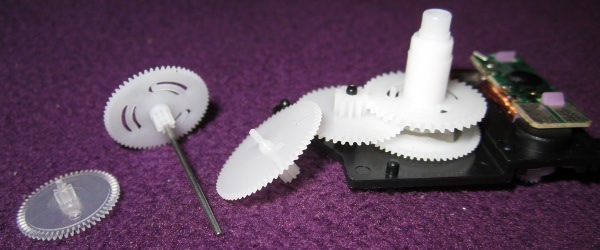
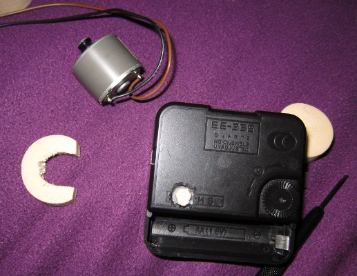
Originally I was planning to directly drive the coil to make the hands move. So I cracked the thing open, soldered the smallest wires I could find to the coil, spent about 2 hours trying to put the damn thing back together again and a couple of days trying to get the damn thing to tick. Finally I realized that even if I did get the thing to tick, even at slightly less than one second per tick, it was likely to take several minutes for each update. What I needed was a beefier motor, which I figured I could hook up directly to the gears. I pulled the motor from an old answering machine and after some surgery involving a box knife, part of a cork (Merlot in case you're curious) and a lot of super glue, it worked.
Motor controller
I'll spare you the long saga and just say that if you're planning to build your own H-bridge, don't. After a lot of pain and wasted energy, I just bought a motor controller, L293D (cost: EUR 4.30).Feedback
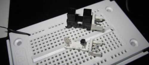
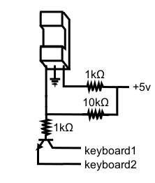
Because I wasn't using a servo or stepper, I needed some way of knowing where the hands were. Using the motor controller, the distance traveled in a given time was pretty consistent, but I still needed occasional feedback. As it happens, I have quite a few optical switches I've salvaged from old printers, so I figured I wire them up to the keyboard to trigger a key press each time the second hand passed through them. I'd never used an optical switch before, guessed how to wire them up, guessed at the circuit, voltage and resister values, and so of course it was the only part of the project that worked the first time. You can see the circuit I used below.
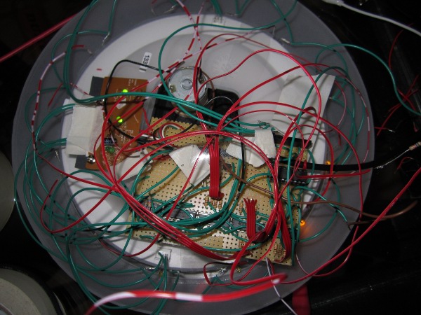
Extra touches
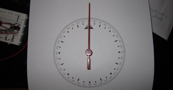
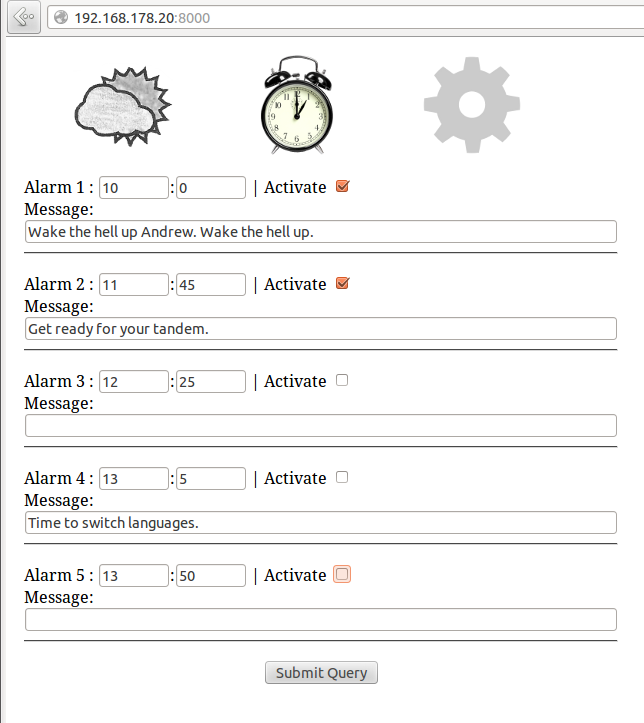
Making the face was pretty straight forward, but fun nevertheless. I owe a debt to Sean Carney and his website (dead link) for the basic design. After designing the face, I printed in balck and white and colored in with crayons (every project is better with crayons). Then it was just a matter of gluing it to the clock and cutting out some holes for the switches. Since I had some extra data lines, I figured I should do something with them. I had a bunch of extra LEDs lying around, so I decided to use 12 of them to show the time. As you'll see in the end, this made for some wonderful wire spaghetti. I also used three LEDs hidden behind the three suns in my weather icons as extra status indicators. One shows if there was an error, one shows when I've received a new comment to my website. The third isn't currently used. Suggestions are welcome. Finally, although it has nothing to do with the weather clock itself, I added some alarms, which are spoken by the computer using eSpeak. When the first alarm is activated, the computer also reads me out the day's full weather forecast.Software
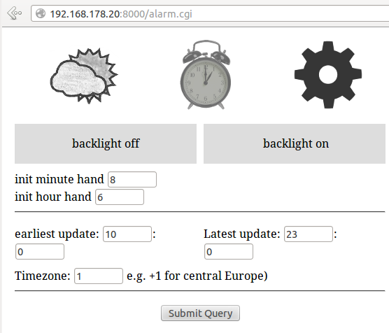
In the end, I wrote everything from scratch. The OLPC runs a little server, which serves up a small app for configuring the clock. I formatted the pages so I could load them on my Nook.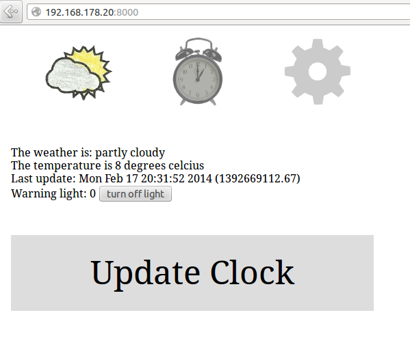
Wrap up
In the end with all the odds and bobs, this probably cost me around 10 euros above what I had on hand. Here's what it looks like in action:
EDIT 20, Feb, 2014
This project has been featured on Hackaday: https://hackaday.com/2014/02/20/weather-clock-puts-olpc-to-work/
Leave a comment